—– 3DPAD.CO.UK – PROFESSIOAL FINISHING
BRASS
HEAT-SET
INSERTS
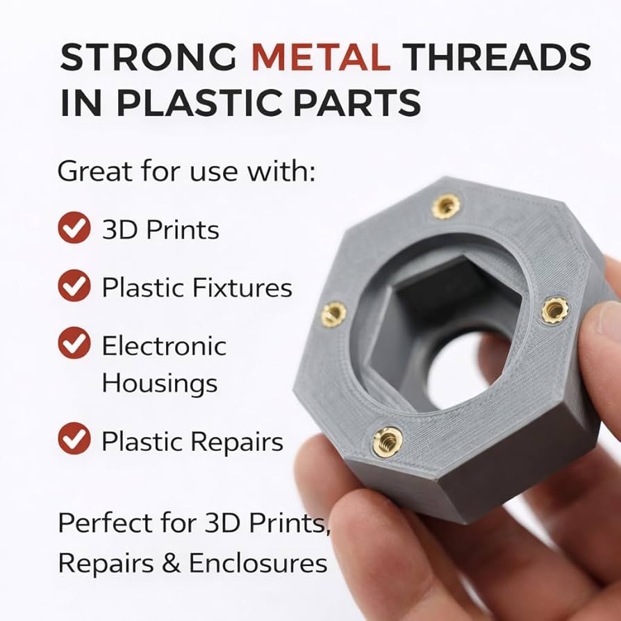
Transform your 3D printed parts from fragile prototypes into production-grade assemblies. Threaded brass inserts give you metal-strength fastening – permanently.
10X
Stronger than plastic threads
M2-M8
Full size range stocked
24-72HR
Turnaround available
THE TECHNOLOGY
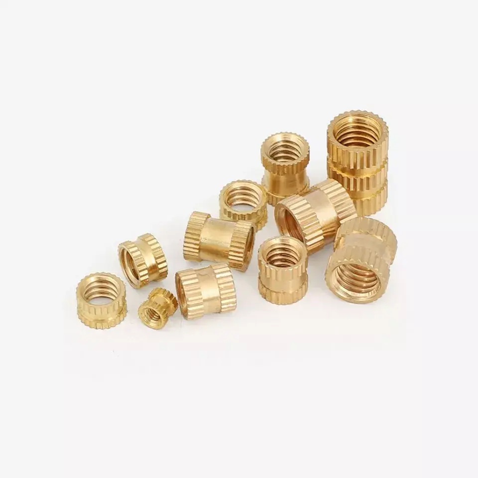
WHAT ARE HEAT-SET BRASS INSERTS?
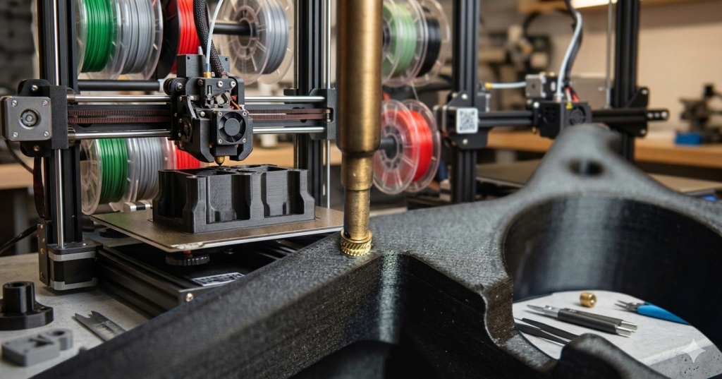
Brass heat-set inserts are threaded metal cylinders designed to be embedded permanently into thermoplastic 3D printed parts. By applying localised heat – typically with a soldering iron or dedicated insert press – the surrounding plastic softens and flows around the insert’s knurled exterior.
When the plastic cools, it solidifies around the insert’s ridges, undercuts and knurling, creating a mechanical lock that resists both pull-out and torque forces far beyond what plastic threads alone can achieve.
Unlike self-tapping screws that cut into plastic (weakening it with every insertion), brass inserts allow repeated assembly and disassembly without degradation – making them the professional standard for engineering prototypes, enclosures, robotics, RC models and consumer product development.
At 3DPAD, we install inserts to exacting tolerances – perfectly flush, perpendicular, and thermally set – so your parts arrive ready to assemble.
PROCESS
HOW INSTALLATION WORKS
Professional insert installation is a precise, repeatable process. Here’s exactly what happens when we work on your parts.
📐—————01
HOLE PREPARATION
Your 3D printed part is designed with a pilot hole slightly smaller than the insert’s outer diameter. This is typically the insert’s OD minus 0.1–0.3mm – enough for plastic to melt into the knurling.
🔥————–02
HEAT APPLICATION
A calibrated soldering iron set to 200–260°C (material-dependent) is applied to the top of the insert. The brass conducts heat evenly into the surrounding plastic, softening it without scorching.
⬇️—————03
CONTROLLED INSERTION
The iron is withdrawn and the part cools. Plastic re-solidifies around every ridge, groove and undercut of the insert – creating a permanent mechanical bond with far superior pull-out and torque resistance.
❄️—————04
COOLING & LOCK
Your 3D printed part is designed with a pilot hole slightly smaller than the insert’s outer diameter. This is typically the insert’s OD minus 0.1–0.3mm – enough for plastic to melt into the knurling.
SPECIFICATIONS
BRASS INSERT SIZE REFERENCE
Full reference table for standard metric heat-set brass inserts. All sizes stocked and available for immediate installation at 3DPAD. Pilot hole sizes are guidelines – always verify with your material and infill.
THREAD SIZE OUTER DIA (OD) STANDARD LENGTH LONG VERSION PILOT HOLE (PLA) PILOT HOLE (PETG) PILOT HOLE (ABS) MIN WALL THICKNESS TYPICAL APPLICTIONS
M2 3.2mm 3.0mm 4.0mm 3.0mm 3.1mm 3.1mm 1.5mm Electronics ----- Tiny enclosures ----- PCB mounts
M2.5 3.8mm 4.0mm 5.0mm 3.6mm 3.7mm 3.7mm 1.8mm RC models ----- Drones ----- Wearables
M3 4.6mm 4.0mm 6.0mm 4.3mm 4.4mm 4.4mm 2.0mm Enclosures ----- Robotics ----- Camera mounts ----- Most common
M4 5.6mm 5.0mm 8.0mm 5.3mm 5.4mm 5.4mm 2.5mm Structural parts ----- Brackets ----- Jigs
M5 7.0mm 6.0mm 10.0mm 6.7mm 6.8mm 6.8mm 3.0mm Heavy-duty ----- Fixtures ----- Industrial
M6 8.4mm 8.0mm 12.0mm 8.0mm 8.1mm 8.2mm 3.5mm Mechanical ----- Frames ----- Tooling
M8 10.9mm 10.0mm 16.0mm 10.5mm 10.6mm 10.7mm 4.5mm Large structural ----- High load ----- Automotive
All dimensions in millimetres. Pilot hole sizes are starting recommendations – adjust ±0.1mm based on your printer’s dimensional accuracy and material shrinkage. Higher infill (≥40%) is recommended around insert locations.
EXPERT GUIDANCE
DESIGN & INSTALLATION TIPS
Whether you’re designing parts for us to finish, or learning the craft yourself – these are the principles that separate professional results from amateur mistakes.
🎯
INFILL MATTERS
Always use minimum 40% infill – ideally 60%+ – in the region around insert holes. A high-infill zone ensures there is enough plastic material for the insert to grip. Gyroid or grid infill patterns distribute stress best around the insert’s knurling.
⚙️
COUNTERBORE DESIGN
For a truly professional finish, design a shallow counterbore (0.5mm deep) around the top of the pilot hole. This creates a ledge that ensures the insert sits perfectly flush – and prevents the plastic from mushrooming up around the insert head during installation.
📏
PILOT HOLE TOLERANCE
Your pilot hole should be 0.2–0.4mm smaller than the insert’s outer diameter. Too small and the insert won’t seat; too large and pull-out strength drops dramatically. Always calibrate your printer with a test block before production runs.
🔩
WALL THICKNESS RULES
Maintain at least 2× the insert OD as the wall thickness from the insert centreline to the outer wall. For M3 inserts (4.6mm OD), that means a minimum 4.6mm of plastic on all sides. Less than this risks the insert pulling out laterally under load.
🌡️
TEMPERATURE CONTROL
Iron temperature should be set 20-40°C above your filament’s glass transition temperature – not the printing temperature. For PLA this is ~180°C, PETG ~220°C, ABS ~240°C. Too hot scorches the plastic; too cold means the insert won’t seat cleanly.
🏗️
PRINT ORIENTATION
Orient your print so that insert holes are printed vertically (hole axis is Z-axis). This eliminates layer lines in the critical bonding zone and maximises pull-out resistance. Horizontal holes through layer lines have up to 40% less holding strength.
MATERIAL GUIDE
FILAMENT COMPATIBILITY
Heat-set inserts work with all common thermoplastics. Here are the materials we process daily at 3DPAD, along with key installation parameters.
175°C
PLA
Most common. Excellent results. Low temp iron required – avoid overheating.
_______________________________________________________
220°C
PETG
Great strength. Slightly flexible. Bonds extremely well around knurling.
_______________________________________________________
240°C
ABS
High heat resistance. Ideal for functional parts. Good pull-out strength.
_______________________________________________________
250°C
ASA
UV stable. Excellent for outdoor parts. Similar to ABS in insert behaviour.
_______________________________________________________
230°C
TPU
Flexible filament. Inserts work – but may pull through under high load. Reinforce locally.
_______________________________________________________
260°C
Nylon
Engineering grade. Superb strength with inserts. Hygroscopic – dry before printing.
_______________________________________________________
240°C
HIPS
Similar to ABS. Good dimensional stability. Works well as a structural material.
_______________________________________________________
280°C
PC
Polycarbonate. Highest strength. Best results of all materials. Challenging to print.
_______________________________________________________